I present here my derpy graduation cap, based off of http://learn.adafruit.com/rgb-led-strips/overview:
 |
| thanks Jamison (http://thevariableconstant.blogspot.com/) for the picture! |
Here it is, just finished at MITERS and still tethered to a power supply. Later I electrical taped on a lipo battery, I kid you not.
From the front it looks normal, which is unfortunate for the graduation video, but whatever, I tried.
 |
| what it looks like from the side. yea I can't believe it got through security too, especially after Jordan's kawaiicopter cap that she worked on all winter break was rejected :'( |
The original plan was to have a spinning RGB POV display, ala the plenitude of persistence of vision clock displays out there.
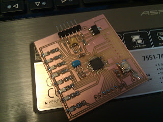
I even milled out a board for it, based on the fabduino files.
 |
| cute non-RGB 7 LED pov board |
I can upload the eagle files if anyone wants, but since I haven't gotten it to work and I can't be sure there's nothing wrong with the circuit I don't want to put the effort into putting it up. This was my first exploration of the autoroute tool, which seemed to work pretty well.
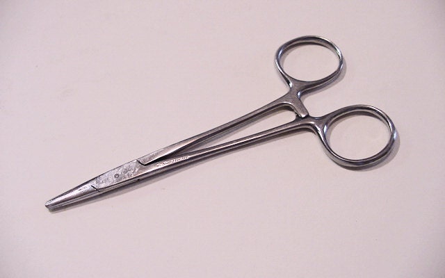
I also found this tool supppeerr useful, way more useful than the helping hands, for holding thick and relatively unyielding wires together so that I could solder them:
 |
| src: http://img2.etsystatic.com/000/0/5195669/il_340x270.329862126.jpg http://www.etsy.com/market/surgeon_tools?ref=listing_tag |
I also would have taken off my cap and showed it to the camera as I was coming down the ramp after getting my diploma if I knew how graduation worked.
I should have sanded down all the wires because I think a lot of the joints were cold solder joints (this bit me when I was repositioning the letters), but it worked okay and is probably the most robust of all the projects I've done so far because the circuit is encased in hot glue. Sorry arduino mini! (I potted that into the breadboard). The circuit itself is super straightforward, 3 FETs directly driven by the arduino. See http://learn.adafruit.com/rgb-led-strips/overview.
 |
| This is what graduation looked like for the parents. |
========================
APPENDIX: Milling circut boards on a Roland modela mill (in the IDC)
========================
Ultimate lesson learned: Make your traces at least 16 mil, 12 mil does not work!
https://github.com/
It's a 5 LED font.
The fabduino I will be running (a waste to use it for just 7 LEDs, but I don't have the time to deal with not just reusing other people's POV code)
How to use the roland modela mill
Eagle libraries
modela@ubuntu:~/Documents/nouyang$ sh eagle-lin-6.4.0.run
1/tmp/eagle-setup.4298/eagle-6.4.0/bin/eagle: error while loading shared libraries: libssl.so.1.0.0: cannot open shared object file: No such file or directory
ugh, let's try troubleshooting this
sudo apt-get install libssl-dev
modela@ubuntu:~/Documents/nouyang$ lscpu
Architecture: x86_64
CPU op-mode(s): 32-bit, 64-bit
Uhmm... okay nope. Switching back to a windows computer. A shame. : / I really ought to switch over to something more happy running on ubuntu someday.
Pin mapping
http://arduino.cc/en/Hacking/PinMapping168
FTDI headers:
DTR,
How to create board outline in eagle:
http://www.electro-tech-online.com/general-electronics-chat/31558-problem-cad-eagle-how-draw-board-space.html
Eagle MAS.863 documentation
Pin mapping
http://arduino.cc/en/Hacking/PinMapping168
FTDI headers:
DTR,
How to create board outline in eagle:
http://www.electro-tech-online.com/general-electronics-chat/31558-problem-cad-eagle-how-draw-board-space.html
Eagle MAS.863 documentation
http://fab.cba.mit.edu/classes/MIT/863.09/people/hannah/modela.html
Design rules:
http://academy.cba.mit.edu/2012/labs/providence/tutorials/07.html
http://fab.cba.mit.edu/content/processes/PCB/
http://academy.cba.mit.edu/classes/electronics_design/index.html
5V 1A regulator is in a SOT-223 package
Fab lab inventory
http://fab.cba.mit.edu/about/fab/inv.html
LM2940IMP-5.0CT-ND
http://octopart.com/datasheet/lm2940imp-5.0%2Fnopb-national+semiconductor-1009434-134675
input gnd output
hmm tangent about IC naming (78xx = vreg)
http://blog.screamingcircuits.com/2013/01/more-cautionary-tails.html
Hmmm eagle files for this vreg
https://www.sparkfun.com/products/595
gnd out in, so pin assignments are wrong, should be easy fix
https://github.com/sparkfun/SparkFun-Eagle-Libraries
https://github.com/sparkfun/SparkFun-Eagle-Libraries/blob/master/SparkFun-PowerIC.lbr
MAke sure to download zip file! OTherwise file does not download properly (adds some html comments at the beginning)
Currently the Vreg-LM1117 package is
1 ADJ
3 IN
2 OUT
4 OUT@1
which matches the datasheet https://www.sparkfun.com/datasheets/Components/FAN1117A.pdf 1:GND, 2:OUT, 3:IN.
However for the LM2940 I want
1:IN 2:GND 3:OUT
Steps ish (very incomplete)
Library>Open>Sparkfun-PowerIC
LIbrary>Device>LM1117
Connect> Disconnect all of them
Create new device
Grid dimensions in autorouting:
https://forum.sparkfun.com/viewtopic.php?p=76309
Export dpi?
http://academy.cba.mit.edu/2012/labs/providence/tutorials/07.html
Correction! It should be both the top and pads layer.Design rules:
http://academy.cba.mit.edu/2012/labs/providence/tutorials/07.html
http://fab.cba.mit.edu/content/processes/PCB/
http://academy.cba.mit.edu/classes/electronics_design/index.html
5V 1A regulator is in a SOT-223 package
Fab lab inventory
http://fab.cba.mit.edu/about/fab/inv.html
LM2940IMP-5.0CT-ND
http://octopart.com/datasheet/lm2940imp-5.0%2Fnopb-national+semiconductor-1009434-134675
input gnd output
hmm tangent about IC naming (78xx = vreg)
http://blog.screamingcircuits.com/2013/01/more-cautionary-tails.html
Hmmm eagle files for this vreg
https://www.sparkfun.com/products/595
gnd out in, so pin assignments are wrong, should be easy fix
https://github.com/sparkfun/SparkFun-Eagle-Libraries
https://github.com/sparkfun/SparkFun-Eagle-Libraries/blob/master/SparkFun-PowerIC.lbr
MAke sure to download zip file! OTherwise file does not download properly (adds some html comments at the beginning)
Currently the Vreg-LM1117 package is
1 ADJ
3 IN
2 OUT
4 OUT@1
which matches the datasheet https://www.sparkfun.com/datasheets/Components/FAN1117A.pdf 1:GND, 2:OUT, 3:IN.
However for the LM2940 I want
1:IN 2:GND 3:OUT
Steps ish (very incomplete)
Library>Open>Sparkfun-PowerIC
LIbrary>Device>LM1117
Connect> Disconnect all of them
Create new device
Grid dimensions in autorouting:
https://forum.sparkfun.com/viewtopic.php?p=76309
Export dpi?
http://academy.cba.mit.edu/2012/labs/providence/tutorials/07.html
then export as a png (file -- export -- image)
settings should be MONOCHROME and 500 DPI - this will export a image with white traces.
Make sure the color mode is set to greyscale: image > mode > greyscale
then export Dimenson layer for milling the outside of the board
Remember: the Modela cuts out the DARK and leaves white!
http://academy.cba.mit.edu/2012/labs/providence/tutorials/install_fab_modules.html
just type in
~$ fab
... upon trying to make path:
distance 0.800000, 140873 exterior points remain
Segmentation fault (core dumped)
must run as sudo
~$ sudo fab
just type in
~$ fab
... upon trying to make path:
distance 0.800000, 140873 exterior points remain
Segmentation fault (core dumped)
must run as sudo
~$ sudo fab


No comments:
Post a Comment